

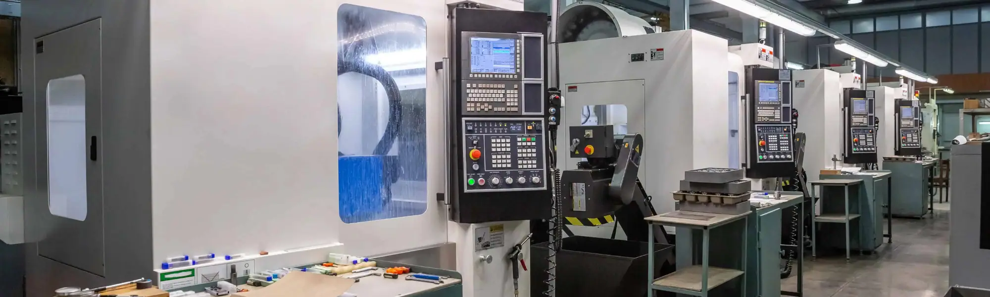
Computer Numerical Control (CNC) machining represents the core of modern subtractive manufacturing. While fabrication processes like structural steel assembly join elements together and sheet metal stamping deforms flat stock, CNC machining cuts away material from a solid block—known as a billet, bar, or casting—to realize a final component with micrometer-level dimensional tolerances and pristine surface finishes. From critical aerospace turbine components, medical orthopedic implants, and high-performance automotive powertrains to custom injection molds and specialized industrial tooling, precision machining delivers an unmatched capability to process complex geometries across a vast range of engineering materials.
Transforming a raw block of metal or polymer into a finished, high-precision component requires a seamless synthesis of digital computer-aided design and manufacturing, advanced machine tool kinematics, cutting tool physics, thermal stabilization, chip control, and rigorous coordinate metrology. Understanding the end-to-end operational lifecycle of precision subtractive manufacturing requires analyzing each core phase: CAD/CAM toolpath generation, machine architecture, cutting dynamics, workholding stability, tool material selection, and modern quality assurance methods.
1. Digital CAD/CAM Integration and Toolpath Generation
The modern CNC machining sequence originates in a digital computer-aided design (CAD) environment, where engineers model the precise three-dimensional solid geometry of the target part. Once the model is finalized, it transitions into Computer-Aided Manufacturing (CAM) software, where manufacturing engineers convert static geometry into dynamic machining operations.
CAM software converts digital surfaces into precise toolpaths by defining cutting parameters such as spindle speed, feed rates, step-over distances, depth of cut, and entry/exit moves. Modern CAM packages utilize advanced feature-recognition algorithms to automatically identify pocket depths, hole diameters, thread pitches, and 3D surface contours.
Key Toolpath Strategies
-
Adaptive Clearing / High-Speed Machining (HSM): Traditional toolpaths often force cutting tools into tight internal corners, causing sudden spikes in tool engagement, excessive heat, and tool breakage. Modern adaptive clearing algorithms dynamically adjust the radial tool engagement, maintaining a constant engagement angle and chip load. This allows the machine to run at substantially higher linear feed rates and axial depths of cut while drastically extending tool life.
-
Trochoidal Milling: A specialized high-speed toolpath technique where the cutter moves in a series of continuous circular loops while advancing along a slot or channel. Trochoidal motion prevents full-width tool engagement, effectively dissipating heat and allowing hard metals—such as titanium or hardened tool steel—to be milled efficiently.
-
Multi-Axis Surface Finishing: For complex 3D organic surfaces, CAM systems generate multi-axis toolpaths that maintain the optimal contact point of a ball-nose end mill or barrel cutter against the workpiece, minimizing cutter deflection and producing ultra-smooth surface finishes.
Once the toolpaths are optimized, a specialized software translator called a Post-Processor converts the CAM vector movements into standard machine code, primarily G-code and M-code. The post-processor is uniquely configured for the specific CNC machine and control architecture (such as Fanuc, Siemens, Heidenhain, or Haas), translating generic vector moves into precise axis rotation angles, linear feed commands, spindle orientation toggles, and coolant activation commands.
2. CNC Machine Tool Architectures and Kinematics
CNC machine tools vary significantly in their mechanical configuration, axis movement capacity, and structural rigidity. The core mechanical framework of a CNC machine is built using heavy gray cast iron, ductile iron, or polymer concrete bases to absorb high-frequency cutting vibrations, resist structural deflection under heavy cutting loads, and maintain thermal mass.
Machine Classifications
CNC Turning Centers (Lathes)
CNC turning centers rotate the workpiece around a central axis while stationary single-point cutting tools feed axially and radially into the material to produce cylindrical components like shafts, bushings, flanges, and threaded rods. Advanced turning centers incorporate live tooling—driven rotary spindles mounted directly on the tool turret—allowing the machine to perform off-center milling, cross-drilling, and keyway slotting without moving the workpiece to a secondary milling machine. Dual-spindle, multi-turret turning centers can process both sides of a complex part simultaneously, delivering finished components in a single setup.
3-Axis Vertical Machining Centers (VMCs)
3-Axis VMCs operate along three linear Cartesian axes: X (left/right table movement), Y (front/back table movement), and Z (vertical spindle movement). VMCs are widely used for prismatic parts, plate work, surface milling, and hole patterns. However, components requiring machining on multiple sides must be manually unclamped, flipped, and reclamped in secondary fixtures, which increases cycle time and introduces potential stacking alignment errors between setups.
5-Axis Machining Centers
5-Axis CNC machines introduce two rotational axes (commonly designated as A, B, or C) in addition to the standard X, Y, and Z linear axes. 5-axis machines operate in two distinct modes:
-
3+2 Axis Machining (Positional 5-Axis): The rotational axes tilt and orient the workpiece to a fixed angular position, allowing a standard 3-axis machining operation to occur from multiple sides without manual re-fixturing.
-
Continuous 5-Axis Machining: All five axes move simultaneously in continuous sync during the cutting operation. This capability is essential for sculpting complex, freeform organic geometries such as aerospace impellers, turbine blades, complex automotive intake ports, and orthopedic hip joint prostheses. Continuous 5-axis motion maintains the cutting tool at its ideal orientation relative to the workpiece surface, maximizing tool stiffness and eliminating cutter tip drag.
3. Cutting Tool Materials, Geometries, and Wear Physics
At the point of cut, the cutting tool experiences intense mechanical stresses, high localized friction, and extreme temperatures that can easily exceed 1,000°C (1,832°F). Selecting the correct tool material, edge geometry, and surface coating is critical to achieving stable metal removal and precise dimensional control.
Tool Substrates
-
High-Speed Steel (HSS) and Cobalt Steel: High-toughness alloys capable of absorbing heavy impact loads without chipping. HSS tools are flexible and cost-effective, but possess limited heat resistance, restricting their use to low-speed operations, manual machinery, or soft aluminum alloys.
-
Micrograin Solid Carbide: The industrial standard for modern CNC tooling. Carbide tools are manufactured by sintering tungsten carbide powder with a cobalt binder matrix. Micrograin carbide provides exceptional hardness, high compressive strength, and thermal resistance, allowing for extremely high spindle speeds and rapid metal removal rates.
-
Indexable Ceramics: Ceramic inserts (such as silicon nitride or aluminum oxide) retain their structural hardness at extreme cutting temperatures. They are used primarily for high-speed roughing of nickel-based superalloys (like Inconel) and hardened steels, operating at speeds up to ten times faster than solid carbide.
-
Cubic Boron Nitride (CBN) and Polycrystalline Diamond (PCD): CBN is the second-hardest known material, ideal for precision finishing of hardened ferrous metals (hard turning). PCD features a layer of synthetic diamond fused to a carbide substrate, providing unmatched wear resistance when machining highly abrasive non-ferrous materials, such as high-silicon aluminum alloys, carbon fiber reinforced polymers (CFRP), and engineering ceramics.
Tool Geometry and Coatings
The physical geometry of a cutting tool determines chip formation dynamics and force distribution. Key geometric features include:
-
Helix Angle: The angle formed between the center axis of the tool and the cutting edge. Higher helix angles (45 to 60 degrees) produce a smooth, shearing action, reducing cutting forces and delivering superior surface finishes on sticky materials like stainless steel and aluminum. Lower helix angles (30 to 35 degrees) provide maximum core strength for heavy roughing in hard steels.
-
Rake and Relief Angles: Positive rake angles reduce cutting forces and minimize work-hardening, while negative rake angles strengthen the cutting edge for heavy, interrupted cuts.
To further resist heat and friction, cutting tools are coated with ultra-thin, hard physical vapor deposition (PVD) or chemical vapor deposition (CVD) ceramic films. Common industrial coatings include Titanium Aluminum Nitride (TiAlN), which forms a protective aluminum oxide layer at elevated temperatures; Titanium Carbonitride (TiCN), offering low friction for abrasive wear; and Diamond-Like Carbon (DLC), which prevents soft metals like aluminum from galling and welding to the tool flute edges.
4. Workholding Stability and Fixturing Dynamics
No matter how rigid a CNC machine tool is, it cannot produce a precise component if the raw workpiece shifts, flexes, or vibrates under cutting loads. Workholding is the engineering art of locating and clamping a workpiece securely in a repeatable location within the machine’s coordinate space.
Locating Principles: The 3-2-1 Rule
To fully constrain a rigid solid body in 3D space, all 12 degrees of freedom (6 translational and 6 rotational) must be locked. The industry-standard locating method follows the 3-2-1 rule:
-
Primary Plane (3 Points): Three locator points define a flat reference base plane, eliminating 3 degrees of freedom (1 translational movement and 2 rotational tilts).
-
Secondary Plane (2 Points): Two locator points along an adjacent perpendicular edge define a line, eliminating 2 degrees of freedom (1 translational movement and 1 rotational twist).
-
Tertiary Plane (1 Point): One final locator point on an end face establishes the exact longitudinal position, eliminating 1 degree of freedom (the final translational movement).
Advanced Workholding Solutions
-
Precision CNC Vises: Standard precision vices feature hardened ground steel jaws and angled internal ramps that pull the workpiece downward as side clamping pressure is applied, preventing part lift during heavy cuts.
-
Modular Fixturing and Tombstones: High-volume horizontal machining centers (HMCs) utilize large multi-sided vertical cast-iron blocks called tombstones. Multiple workpieces are mounted on each face using quick-change fixture plates, allowing the machine to run unattended for hours.
-
Vacuum and Magnetic Chucks: Vacuum tables support thin, flexible sheet stock, composite plates, or thin-walled aerospace skins without applying concentrated side clamping forces that would distort the finished geometry. Permanent electro-magnetic chucks secure thick steel plates, providing unobstructed 5-sided tool access.
-
Zero-Point Clamping Systems: These baseplate receiver systems allow complete fixture assemblies to be locked into or released from the machine table within seconds, maintaining positional repeatability of less than 2 micrometers. This capability allows manufacturers to load and setup raw parts on external fixture plates outside the machine while the CNC continues running a separate job inside, maximizing spindle utilization.
5. Thermal Management, Coolants, and Chip Control
The physical act of cutting metal converts virtually all applied mechanical mechanical work into heat through primary shear zone deformation and secondary friction against the tool face. Uncontrolled heat causes thermal expansion of both the cutting tool and the workpiece, leading to dimensional drift, poor surface finishes, and rapid tool degradation.
Chip Formation Mechanics
Efficient cutting relies on forming correct, manageable chips. As the tool edge penetrates the metal, material undergoes severe shear strain along the primary shear plane, forming continuous, discontinuous, or segmented chips depending on the material’s ductility.
The continuous removal of chips serves an essential function: a well-formed chip carries away roughly 80% of the generated heat, preventing heat from sinking into the parent workpiece or cutting tool. Modern cutting tools feature engineered chip-breaker grooves ground directly behind the cutting edge. These grooves force the hot, continuous ribbon of metal to curl tightly until it breaks into manageable, C-shaped or 6-shaped fragments that easily flush out of the cutting zone.
Coolant Delivery Systems
-
Flood Coolant: High-volume streams of water-soluble oil emulsion continually flood the tool-workpiece interface. Water provides rapid heat extraction, while oil lubricates the contact zone and protects the machine against internal corrosion.
-
High-Pressure Through-Spindle Coolant (TSC): Coolant is pumped at extreme pressures (ranging from 500 to 2,000 PSI) directly through internal fluid channels running down the center of the spindle and out the core of the cutting tool. TSC blasts chips out of deep holes, prevents chip recutting during deep pocket milling, and provides immediate thermal cooling directly at the cutting tip.
-
Minimum Quantity Lubrication (MQL): MQL replaces flood coolant with an ultra-fine, metered aerosol mist of vegetable or synthetic oil propelled by dry compressed air. MQL drastically reduces liquid chemical waste, eliminates the need for messy workpiece cleaning, and lowers disposal costs while providing sufficient micro-lubrication for high-speed machining operations.
6. Metrology, Quality Assurance, and Surface Finish Analysis
The final step in precision CNC machining is metrology—the scientific verification that the physical part matches the exact dimensions, geometric tolerances, and surface parameters called out on the engineering drawing.
Geometric Dimensioning and Tolerancing (GD&T)
Modern engineering drawings rely on Geometric Dimensioning and Tolerancing (GD&T) according to ASME Y14.5 or ISO standards. GD&T defines explicit control frames for form, orientation, profile, and location relative to designated datum references. Rather than simply applying linear dimensional limits (such as plus-or-minus 0.05 mm on length), GD&T controls characteristics such as:
-
Flatness and Straightness: Ensuring surfaces do not bow or warp.
-
Cylindricity and Concentricity: Controlling roundness and central alignment along revolving axes.
-
True Position: Defining a precise 3D cylindrical tolerance zone within which the central axis of a hole or feature must reside relative to key reference datums.
Precision Measurement Tools
Coordinate Measuring Machines (CMM)
A CMM uses a high-precision, air-bearing touch-trigger probe or continuous analog scanning probe to record 3D point coordinates across the part surface. Driven by automated measurement routines, CMMs map complex features relative to reference datums with sub-micrometer measurement accuracy. Fixed laboratory CMMs operate inside climate-controlled cleanrooms maintained at exactly 20°C (68°F) to eliminate thermal material expansion during verification.
On-Machine CNC Probing
Modern CNC machines integrate wireless optical or radio-frequency touch probes directly into the tool spindle. On-machine probes check raw stock alignment before cutting, measure critical features between roughing and finishing passes to compensate for tool wear automatically, and verify final dimensions before the part is removed from the fixture.
Surface Roughness Metrology
Surface texture is critical for sliding contact surfaces, hydraulic seals, and fatigue-sensitive aerospace parts. Surface finish is measured using a diamond-stylus profilometer that tracks minute vertical surface peaks and valleys.
-
Ra (Roughness Average): The arithmetic average of absolute surface height deviations measured across a specified evaluation length. High-precision CNC milling typically achieves Ra values between 0.8 and 1.6 micrometers, while precision grinding and superfinishing achieve Ra values below 0.1 micrometers.
-
Rz (Maximum Peak-to-Valley Height): The average distance between the highest peak and lowest valley over individual sampling lengths, providing crucial insight into localized scratches or micro-cracks that could serve as stress concentration points for fatigue failure.
Stainless steel pipes kampala uganda